Confidence in a simulated vehicle’s ability to replicate real-world behavior is fundamental to virtual development. For engineers designing ADAS and autonomous systems, this confidence depends on the fidelity of the underlying vehicle model and the controllers driving it. If the simulated vehicle does not respond as its physical counterpart would, every downstream test, from control logic to perception, risks being built on false assumptions.
To address this challenge, Ford Otosan partnered with Applied Intuition to integrate high-fidelity TruckSim vehicle dynamics models with the Applied Development Platform (ADP) and Ford Otosan's proprietary low-level controllers. This collaboration demonstrates how accurate vehicle modeling and real-world controller integration can provide a trusted foundation for virtual validation.
VehicleSim, the umbrella suite of CarSim, TruckSim, BikeSim, and SuspensionSim, is widely recognized as an industry standard for physics-based modeling. Each product is integrated directly into Applied Intuition’s simulation ecosystem to support high-fidelity dynamics across a variety of vehicle platforms. Ford Otosan leveraged TruckSim to create a detailed, physics-driven truck model as the foundation for their virtual testing and controller validation.
These tools enable an ADAS engineer, not a vehicle dynamics specialist, to move the needle on their vehicle model. By switching from a simplistic kinematic bicycle model to a TruckSim model, results improve drastically. The increase in fidelity is well worth the effort, even if the ADAS engineer may incorporate more assumptions into their high-fidelity models.
The goal: to build a virtual truck that behaves indistinguishably from its physical counterpart. With this level of correlation, Ford Otosan can develop, evaluate, and validate ADAS and autonomous systems primarily in simulation—reducing the cost, time, and risk associated with physical test drives.
Ford Otosan’s Goals
Ford Otosan’s focus on high‑fidelity simulation aligns with Applied Intuition’s mission to accelerate the world’s adoption of safe and intelligent machines. Together, the teams built a workflow that enables engineers to develop, test, and validate software using trusted, physics‑based vehicle models—reducing the burden of costly and time‑consuming physical tests.
The collaboration began with the parameterization of a base vehicle model, also referred to as the vehicle plant model, followed by the integration of Ford Otosan’s low-level controllers for simulation. These controllers manage and execute control actions for subsystems such as steering, transmission, and braking. Integrating them into the virtual vehicle creates a close representation of real‑world performance.
Ahmet Faruk Keleş, an ADAS SIL/HIL Engineer at Ford Otosan, led the integration of the proprietary control logic into the model. His goal was to achieve a high degree of correlation between the physical vehicle and its simulated counterpart.
“Achieving a close match between the physical truck's behavior and the simulated model provides confidence that the model and workflow are accurate,” Keles said. “This validation is critical for projecting the vehicle's response in further simulations.”
He added, “The main goal of creating a correlated vehicle model is to reduce the dependency on vehicle testing for ADAS development and replace it with SIL, MIL, and HIL workflows. With a correlated model, we can trust that what we observe in simulation matches what occurs on the road. This reduces effort and resources spent on physical testing, particularly during parameter tuning, and creates a safe environment for exploring new feature concepts.”
This goal—grounded in modeling accuracy, controller fidelity, and iterative correlation—sets the foundation for a more efficient virtual development process. With these fundamentals established, the next step is to examine the methodology Ford Otosan used to correlate its vehicle model.
Vehicle Model Methodology
To deliver on vehicle model correlation, Ford Otosan adopted a methodology that systematically verifies model accuracy, then controller integration—ensuring that every simulation step represents real-world behavior.
VehicleSim models are designed to be modular. Applied Intuition provides extremely robust physics models with templates for vehicle subsystems like powertrain, suspension, tires and more. Customers can quickly get started with these templates or they can choose to bring in their own external subsystems.
The majority of vehicle subsystems include control modules, such as traction control systems, or transmission shift controllers for the powertrain. We recognize that these control modules contain a customer’s IP, hence we provide full flexibility to customers to integrate their control strategies into VehicleSim. Running the same controller logic in simulation that runs on-vehicle adds an additional layer of confidence when building a virtual vehicle model. The plant model and control systems work in tandem to provide the best virtual representation of a vehicle.
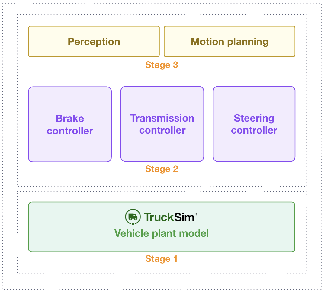
The vehicle model verification process is approached in three steps: open-loop TruckSim model validation, followed by integration of low-level controllers with the TruckSim model, and finally adding any high-level controllers that might be used in AV/ADAS. This project focused only on the first two stages. See Figure 1 to gain a better understanding of a system representation with Stages 1 and 2.
Applied Intuition’s + Ford Otosan’s Approach
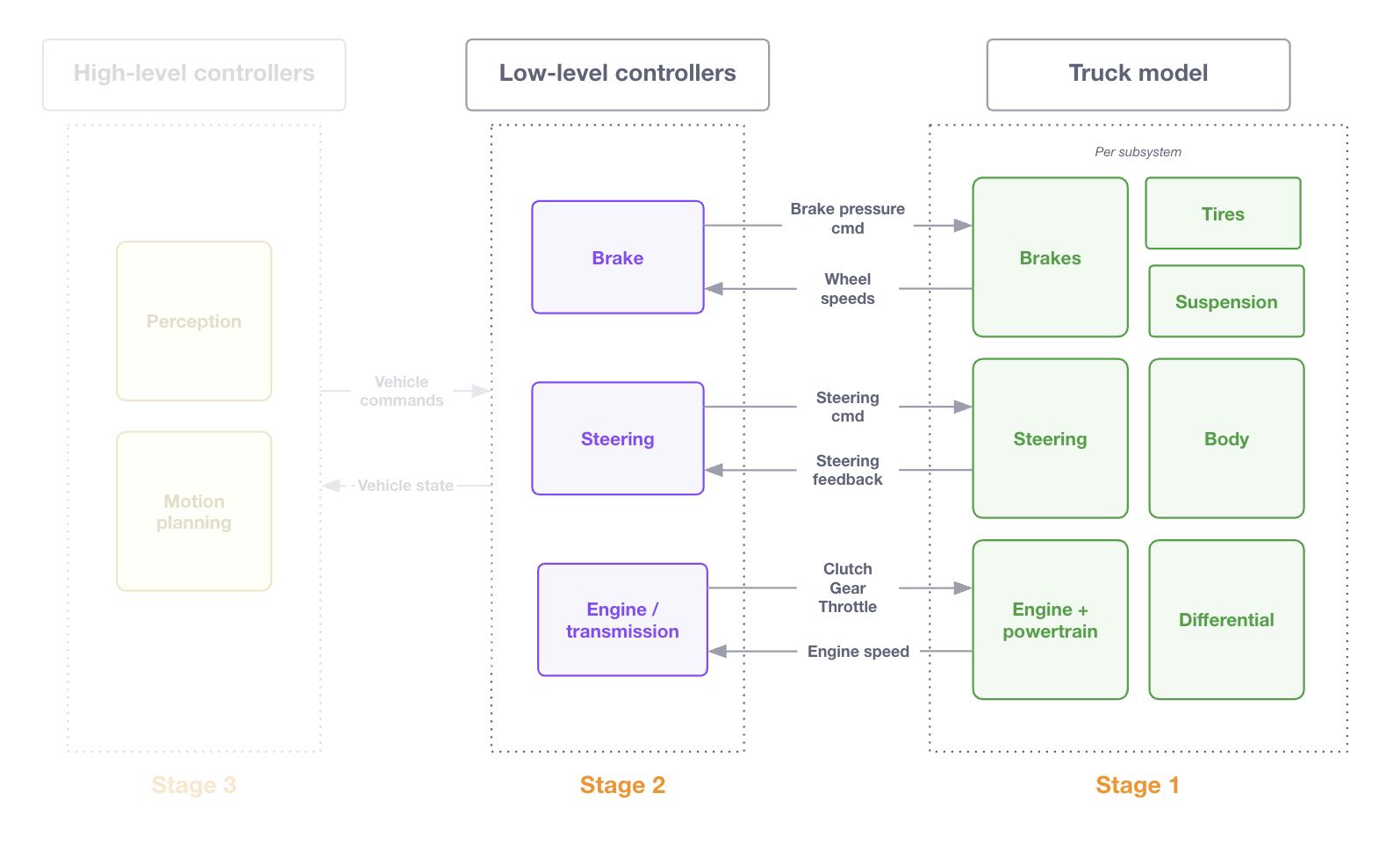
Given the modularity of TruckSim models, Ford Otosan's integration bypasses the internal engine and transmission controllers and directly sends ADAS desired control commands and transmission signals, either from collected vehicle logs or their stack, to drive the wheels. TruckSim's configurable I/O makes this possible. Figure 2 describes the signal exchange between the low-level controllers and the TruckSim module after stage 1 and 2 are completed.
TruckSim is seamlessly integrated into ADP as a selectable vehicle model. ADP allows for the creation of full scenarios to simulate the model and integrated controls with appropriate assumptions. This validation procedure compared test logs of a physical truck to the simulated truck running in open-loop simulation. The test log control signals are directly fed into the simulation, the logs define the scenario and only the ego’s initial position needs to be defined on the map.
An HD map and terrain file of Ford Otosan’s testing area were also imported into ADP. Using the same map in both drive logs and in simulation ensured consistency between the real-world and simulation environments, which is crucial for validating the vehicle model.
Let’s look at Stages 1 and 2 in detail.
Stage 1: Open-loop TruckSim model validation
The first stage focuses on parameterizing the vehicle plant model by using the TruckSim product. TruckSim's system-level math models simulate a vehicle’s physically measured responses without needing detailed knowledge of component materials or intricate suspension designs. To do this, they require data on suspension kinematics and compliances, tire properties, powertrain, brake and steering data, and environmental conditions. This approach ensures the models remain accurate enough for evaluating new designs and control strategies, even with limited reference data.
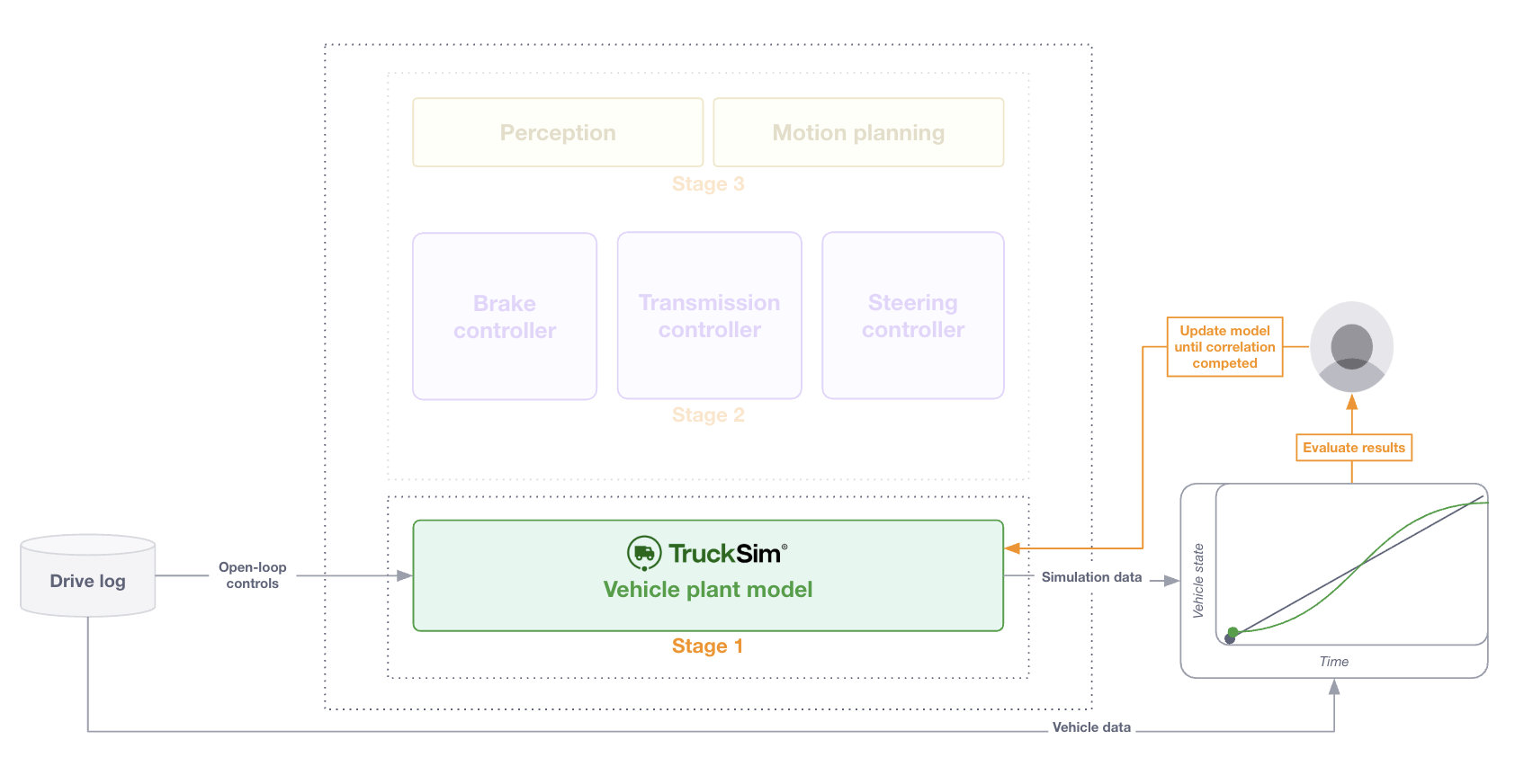
After parameterizing a model, we evaluate the pure dynamic response of the TruckSim model over a broad range of longitudinal and lateral maneuvers. We then verify the model by isolating open-loop controls for throttle, brake, and steering from the collected drive data into the plant model, ensuring the vehicle response matches as expected. Figure 4 explains this process.
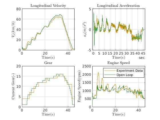
Ahmet’s Stage 1 results compare log data against a TruckSim model. The log’s throttle signal is used as open-loop input to the TruckSim model. In Figure 5, the R2 error is 0.9741.
The TruckSim model should remain unmodified after completion of Stage 1. When correlating the next phase with low-level controllers in the loop, this minimizes the risk of overcompensating sim-to-real gaps from the controls in the vehicle model. This vehicle is representative and will now unmask the controls deficiencies going into the second correlation stage.
Stage 2: Validation with low-level controllers + TruckSim model
The second stage focuses on integrating low-level control logic with the parameterized vehicle model. For example:
- Integrating transmission control logic to command the gear in the vehicle model
- Integrating a brake controller sending desired brake pressure to the vehicle model
Ford Otosan integrated low-level logic for longitudinal and lateral controllers. For longitudinal control, they integrated their brake, and transmission controllers, and for lateral control they implemented their steering controller.
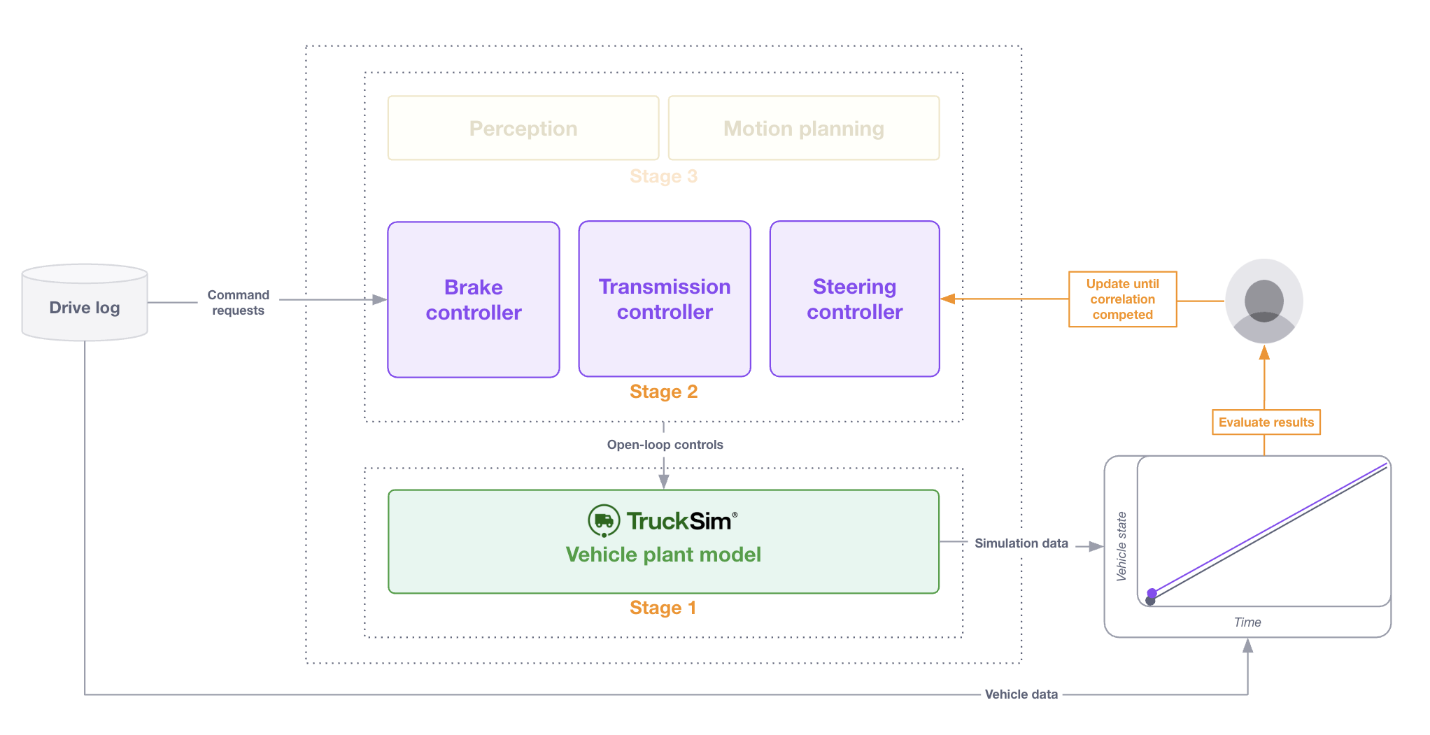
To validate correlation at this stage, we input open-loop data to the integrated low-level controllers. The output of the low-level controllers was then input directly to the vehicle model, and the fully integrated behavior was evaluated in isolation without closed-loop response. Ideally, if controllers have exactly the same interfaces as the real-world systems, no additional correlation effort is required. But if there is any parity difference, the integration requires support from the controls team in calibrating the low-level controllers.
Ahmet’s Stage 2 results compare log data against a TruckSim model with Ford Otosan’s custom controllers. In Figure 7, the R2 error from Stage 1 is 0.9741, whereas results improved to 0.9977 with Ford Otosan’s integrated custom controllers in Stage 2.
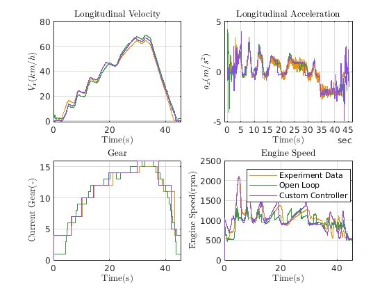
Table 1 captures the results with different error methods applied against the log data, including L2, R2, and Sprague-Geers methods.
Eliminating unknowns as complexity is added to the vehicle model - this is the key advantage to this approach. Since the vehicle model response is already correlated, it can be considered “locked,” and focus can be spent on ensuring the low-level controllers function as expected in the simulation environment. For example, the gain on a yaw controller might be adjusted to compensate for the gap between simulation and real world.
Stage 3: Validation of high-level controls (i.e., ADAS/AV algorithms)
While we focused on vehicle model and low-level controller validation, ADP enables users to rigorously test the full ADAS/AV system, all while using the same high-fidelity VehicleSim model. This ensures a realistic vehicle dynamics response for ADAS/AV development. However, stage 3 is out of scope for this blog post.
Now let’s review the results by maneuver to prove the methodology.
Results and Conclusion
To validate the correlated vehicle model and integrated controllers, Ford Otosan compared real-world test logs with simulation outputs across a series of key scenarios - from longitudinal acceleration and deceleration, to lateral maneuvers such as double lane changes. By evaluating metrics relevant to each scenario, such as vehicle speed, acceleration, gear selection, yaw rate, and lateral acceleration, the team confirmed high agreement between physical and virtual vehicle behaviors.
The correlation of the vehicle’s integrated low-level controllers is complete. Keles concludes, “These results give our ADAS team confidence to trust the results of simulations. With this model, we are sure that the phenomenon we observe in simulation will also be observed in road testing, reducing the need for road tests for controller tuning and ADAS development.” The current snapshot of the TruckSim model is sufficient for Ahmet’s ADAS testing. If Ford Otosan desired to further optimize their model, they could iterate and collect vehicle test data for each vehicle subsystem.
Longitudinal 0 - 60 kph - 0:
This scenario involved testing the vehicle's acceleration and deceleration capabilities. By comparing against the 7 real-world logs and simulated data, we validated the longitudinal dynamics of the model. Vehicle speed, acceleration and gear selection were compared in Figure 8.

Longitudinal velocity:
Double Lane Change:
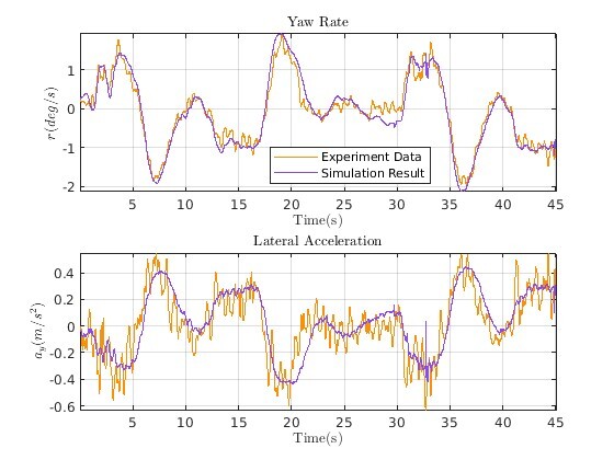
This scenario tested the vehicle's lateral dynamics. Comparing the real-world and simulated data for a lane change helped validate the model's ability to accurately simulate the steering controls and subsystem. In Figure 9, the R2 error for the yaw rate is 0.93 and 0.83 for lateral acceleration.
The log data did not contain roll angle; the relevant yaw rate and lateral acceleration signal that were present in the log data are evaluated.
Yaw Rate:
Lateral Acceleration:
ADAS Development:
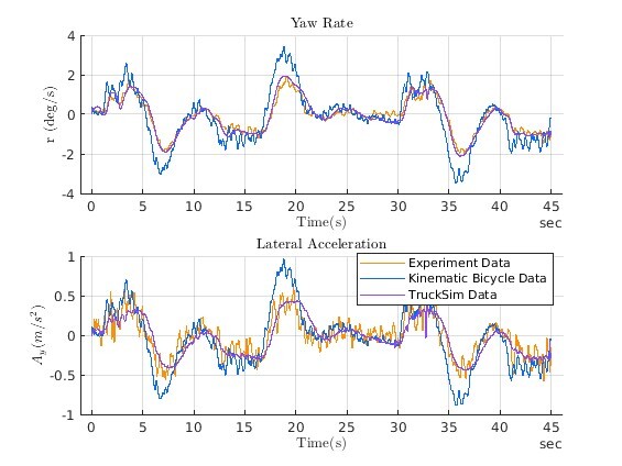
Comparing the correlated model against a simplistic kinematic bicycle model can highlight the importance of using a more detailed model for ADAS development. The difference between the correlated TruckSim model and the kinematic model can demonstrate the value of trust in simulation backed by real data.
The Longitudinal 0 -> 60 kph -> 0 scenario was executed with both the kinematic bicycle and TruckSim models. To run this, acceleration input from the log is normalized to a throttle input, leading to a larger difference in the kinematic bicycle. Figure 10 highlights the gap in acceleration performance with the kinematic bicycle model.
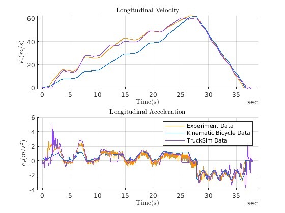
The Double Lane Change scenario was executed with both the kinematic bicycle and TruckSim models. Figure 10 highlights the gap in yaw rate performance the kinematic bicycle model cannot close against the log data and integrated low-level controllers with TruckSim.
Across multiple experiments, the vehicle model and controllers demonstrated tight correlation in both longitudinal and lateral dynamics, as indicated by low L2 and Sprague-Geers errors and high R² similarity. Where discrepancies existed the team acknowledged and documented these factors, maintaining transparency about the strengths and limitations of the model. The largest gaps in the results are due to the following factors:
- Variation in starting position between the log data and simulation (thus some logs might follow a slightly different road gradient),
- A test day with extreme temperatures (altering parameters such as effective rolling resistance and surface mu), and
- Tire and powertrain properties using vehicle-class generic values (for example, some inertias or rotational stiffnesses).
This validation establishes a trusted simulation platform for ADAS development, replacing costly physical testing for many parameter tuning and system validation tasks. As Ford Otosan and Applied Intuition continue to expand their virtual validation workflows, these results demonstrate the real-world efficiency and reliability achievable with high-fidelity vehicle models and integrated control systems.
What’s Next?
As the automotive and trucking industries continue to face challenges from the mounting complexity of software systems, accurate vehicle dynamics remain a crucial element of development. Through this case study with Ford Otosan, we explored how Applied Intuition’s tools support high-fidelity vehicle model validation. As more automotive software development and testing is virtualized, developers can improve their efficiency only by trusting these underlying physics-based models.
Learn how VehicleSim and ADP are enabling next-generation virtual validation for mobility leaders worldwide.
.webp)
.webp)

